Quick Start
A new AutoGen X Pro controller normally goes through four steps: create an account, claim the device using its QR code, connect it to Wi‑Fi, and then open the dashboard to confirm it is online and reporting live values.
Sign in through the mobile app or web dashboard using the account you want to use for everyday monitoring.
Scan the QR code attached to the controller or supplied with the installation package.
Use the Bluetooth Wi‑Fi setup tool in the app to send your network name and password to the controller.
Open the controller dashboard and verify that live readings are updating and the controller shows the expected state.
Before You Begin
- A claimed AutoGen X Pro controller
- The AutoGen mobile app or access to the web dashboard
- Your Wi‑Fi network name and password
- The controller QR code
- Confirm the controller is powered
- Stay close enough for Bluetooth setup during first connection
- Use the same account for claim and daily monitoring unless ownership is being transferred later
Claim Your Device
Claiming links the controller to your account. In the mobile app, open Devices, start the QR scanner, scan the controller QR code, enter a clear device name, and confirm with your account password.
Use clear names such as Home Generator, Workshop Backup, or Site 2 X Pro.
The controller should appear in your device list and become available in both the mobile app and web dashboard.
12-Pin Connector
The AutoGen X Pro uses a 12-pin connector for controller power, relay outputs, and voltage-sensing inputs. Not every installation uses every pin. Some pins are only used when optional sensors or external control methods are installed.
+12 VDC controller power input.-12 VDC common ground.0–60 VDC generator running signal input.0–60 VDC 2-wire start/stop input.Connector Overview
This simplified connector overview shows the main X Pro pins used for power, relays, running signals, choke control, and sensing.

Start Relay Example
This example shows a standard automotive relay used for the generator start circuit.

Stop Relay Example
This example shows a standard automotive relay used for the generator stop circuit.

Connect To Wi‑Fi
AutoGen X Pro is a Wi‑Fi controller. Cloud connectivity is provided by sending your Wi‑Fi credentials to the controller over Bluetooth Low Energy in the AutoGen mobile app. The controller must be joined to a 2.4 GHz Wi‑Fi network before you should expect cloud connectivity.
Open the AutoGen mobile app, go to BLE WiFi Setup, connect to the controller over BLE, enter the local Wi‑Fi name and password, and complete Wi‑Fi provisioning.
The controller normally advertises a Bluetooth name beginning with AutoGen-XPro-.
Use the app status check to confirm whether the controller joined your Wi‑Fi network successfully and then verify that it appears online in the AutoGen cloud.
Mobile App Guide
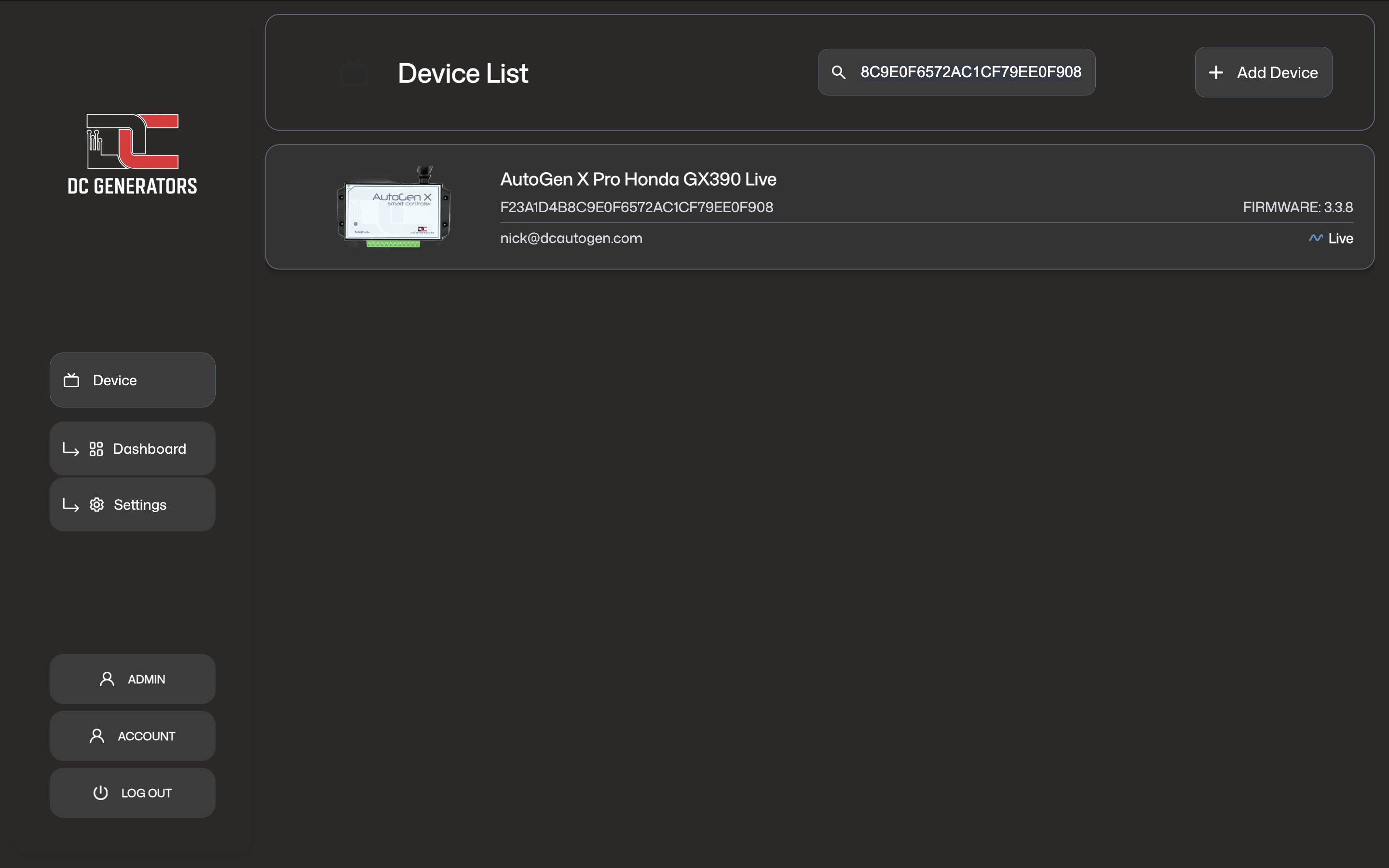
The mobile app is usually the fastest way to claim a controller, connect it to Wi‑Fi, check live readings, and perform normal day-to-day control.
Shows your claimed controllers and gives access to QR claim and device selection.
Shows live readings, controller state, runtime information, and the main control button.
Used when the controller needs to be connected or reconnected to Wi‑Fi.
Main control button
The main button changes with controller state. In standby it shows Start Generator. While the generator is running it changes to Stop Generator. If the controller is in a fault condition, it changes to Reset Generator.
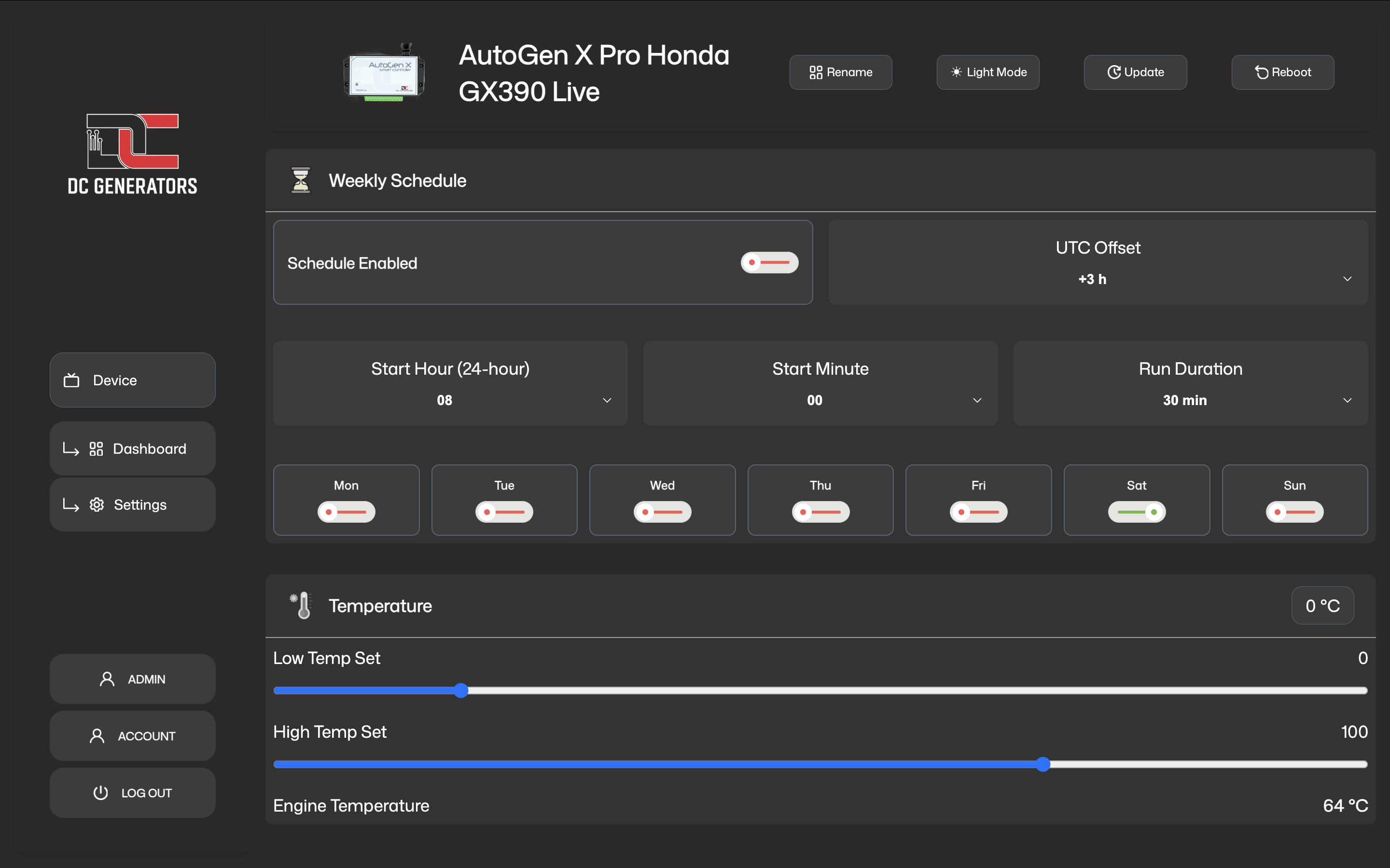
Web Dashboard Guide
The web dashboard gives you a larger management view from a computer or tablet. It is useful for checking live readings, reviewing runtime, adjusting available settings, and performing normal operating actions.
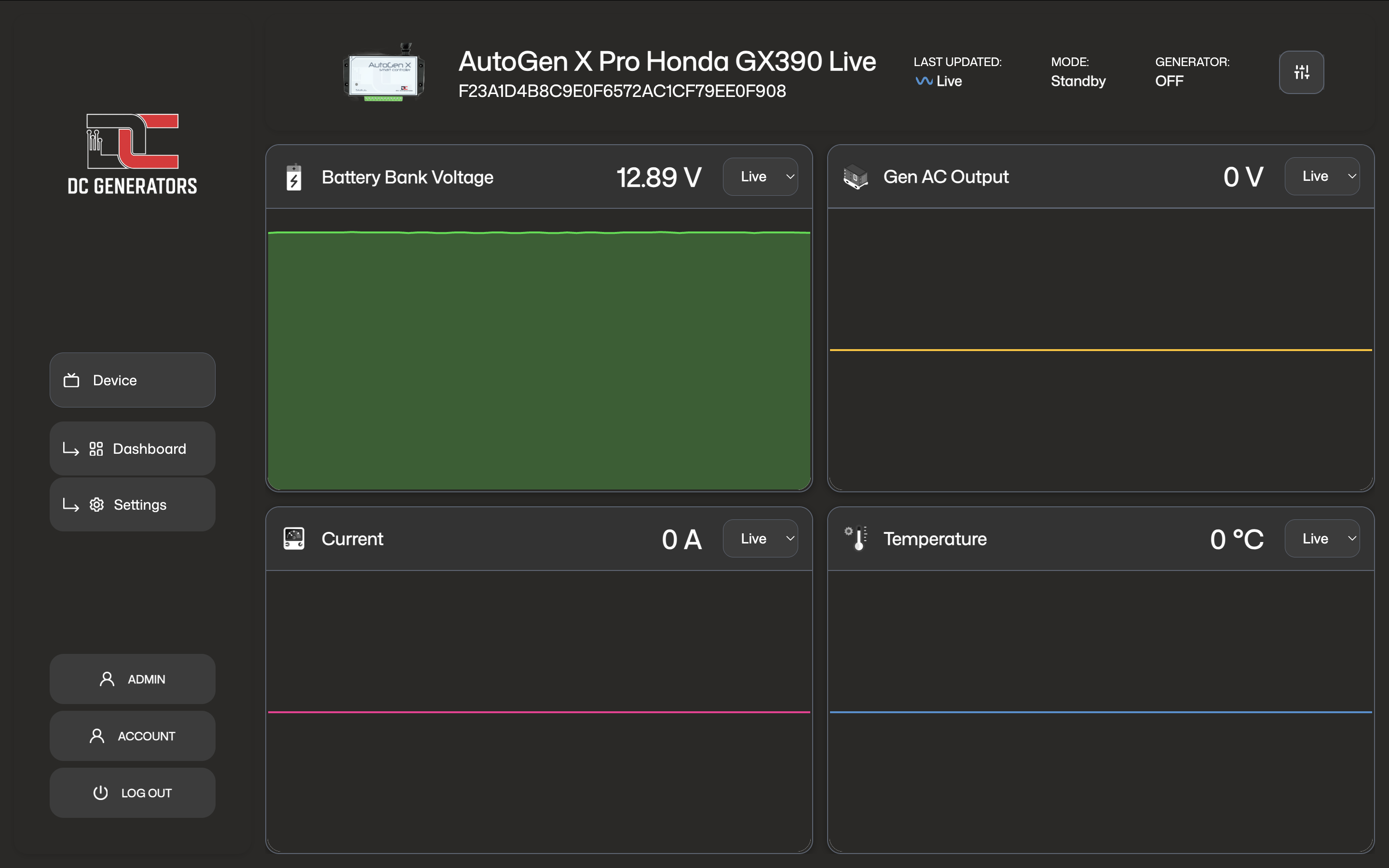
Monitoring And Readings
The controller dashboard focuses on the readings that matter during real operation. These values help you understand whether the generator is waiting, starting, running, shutting down, or protecting itself.
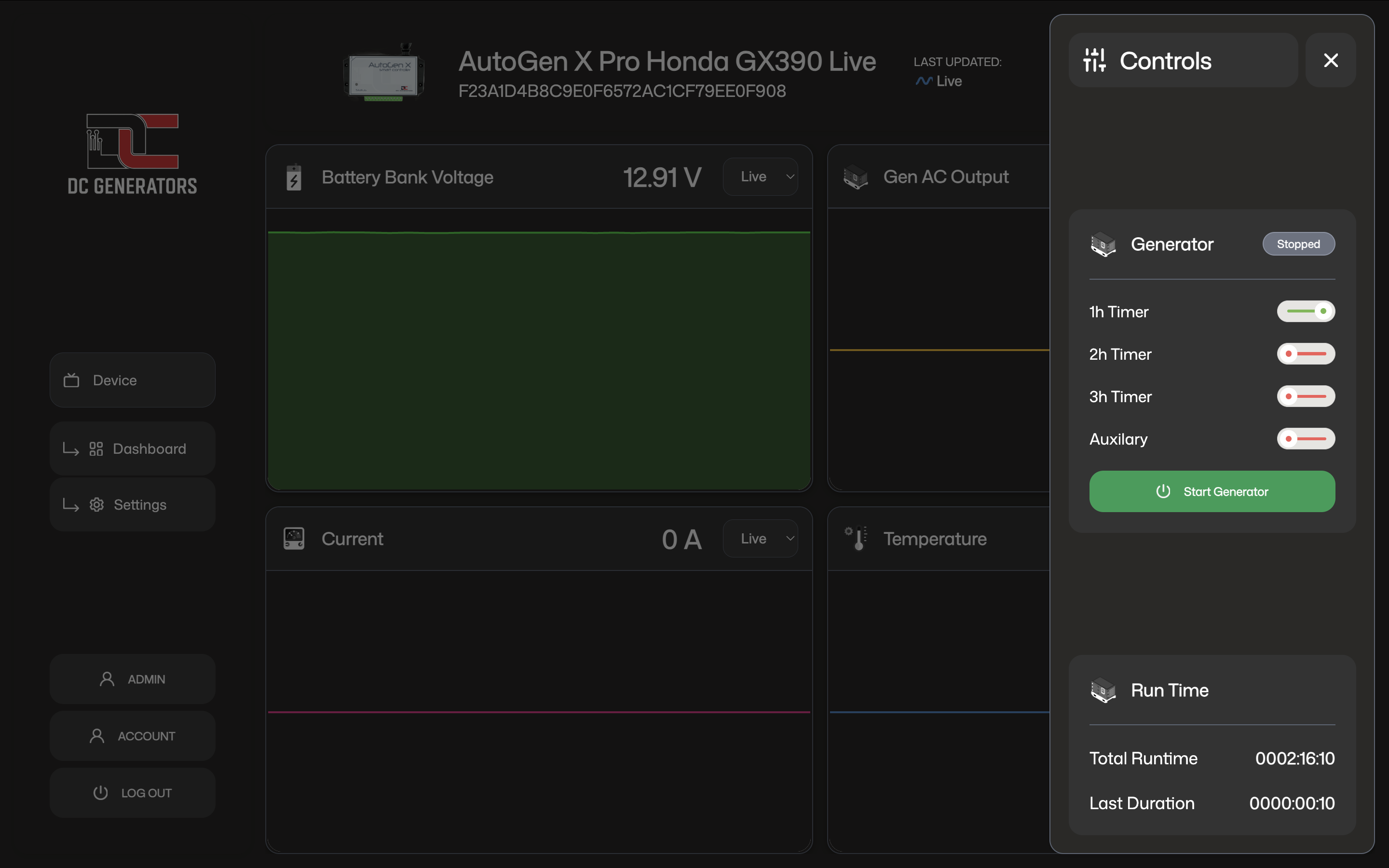
Manual Control
Start and stop are not instant on-off actions. When you press Start Generator, the controller begins a managed start sequence and waits for confirmation that the generator has actually started. If that confirmation is not received, it retries. If repeated attempts fail, the controller enters an error state instead of continuing unsafely.
Used when the controller is ready to begin a run cycle from standby or another valid waiting state.
Used when the generator is running and you want the controller to bring the system back to a stopped or waiting condition.
Reset Generator. Reset clears the fault condition so the controller can return to a normal ready state before another run is attempted.
Automatic Operation
Start by battery voltage
The most common automatic start method is battery voltage. When the battery bank falls below the configured Start Voltage, the controller begins a generator start sequence. This helps protect the battery bank from remaining too low for too long.
Stop by battery voltage
While the generator is running, the controller continues to monitor battery voltage. When battery voltage rises above the configured Stop Voltage, the controller stops the generator because the charge target has been reached.
2-wire external start mode
Some installations use a 2-wire external start signal. In that arrangement, the controller starts when the external start condition is present and stops when that condition is removed and the shutdown logic is satisfied.
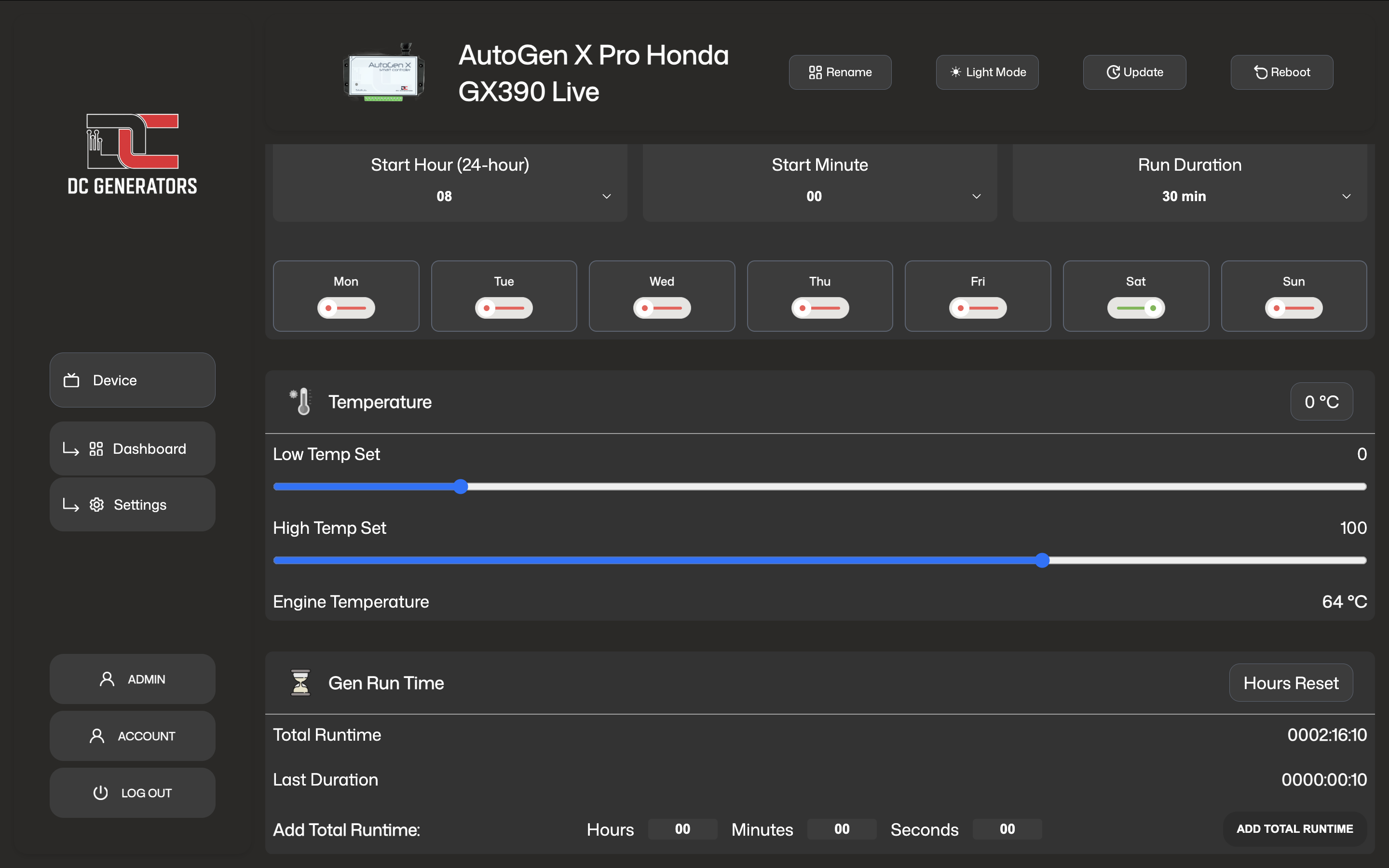
Temperature-based operation
If the measured temperature rises above the configured upper threshold while waiting, the controller can start the generator automatically.
If temperature falls below the configured lower threshold while running, the controller can shut down to protect the system.
Important Settings
Status LED Guide
The status LED is used to show startup, Wi‑Fi provisioning, cloud connectivity, and firmware update activity.
Early startup and hardware initialization are in progress immediately after power-up.
The controller is powered but not yet connected to Wi‑Fi or the AutoGen cloud.
The controller is waiting for Wi‑Fi onboarding during BLE provisioning or SmartConfig-style setup.
The controller is moving through post-startup transition before normal connected operation.
Wi‑Fi is connected and the controller is finishing its connected startup phase.
The controller is connected to the AutoGen cloud and operating normally.
OTA update patterns
The LED alternates red and green three times before the download begins.
The LED blinks red six times, then returns to normal operation.
The LED rapidly alternates blue and cyan while the firmware file is being transferred.
The LED shows blue, white, cyan, then turns off before the controller restarts.
A repeating red SOS-style blink pattern means the firmware update did not complete successfully.
Error States And Recovery
Error states are protective. They do not always mean the controller itself is faulty. In many cases they mean the controller was asked to start or continue running, but did not receive the confirmation needed to continue safely.
The controller attempted to start the generator multiple times but never received reliable proof that it started correctly.
The controller expected the generator to be running, but the signal used to confirm operation no longer matched.
The controller detected a condition that made it unsafe or invalid to continue normal operation.
Timers And Runtime
Run limit timers
Time-limited run options such as 1-hour, 2-hour, or 3-hour operation do not stop the generator immediately. They set a run limit. Once the controller confirms that the generator is actually running, the selected timer begins counting down. When the limit is reached, the controller performs an automatic stop.
The total operating time recorded by the controller over its life, unless it has been intentionally reset.
The duration of the most recent run cycle, or the current cycle while the generator is running.
Hours reset
Hours reset clears the stored total runtime. This is generally a maintenance action and should be used carefully.
Add runtime
Add runtime is used when runtime records need to be corrected manually, such as after service work or replacement of components.
Care And Good Practice
Review voltage, temperature, and state information after installation changes, service work, or unusual generator behavior.
This makes it easier to identify the correct controller in the app and dashboard, especially when more than one unit exists.
Always confirm that the controller changed into a running state and remained there, rather than relying only on the button press.
If faults return repeatedly, investigate the real cause instead of repeatedly clearing the error.