Models Covered
This manual applies to the shared user experience across the main AutoGen generator families:
V5, V100, D100, and D180.
Quick Start
Create or sign in to the AutoGen account you want to use for everyday monitoring.
Scan the QR code linked to the generator and confirm the claim in the app.
Open the device list and verify the generator appears with live or recent activity.
Check voltage, status, and runtime before using any manual or automatic control.
Before You Begin
- The generator QR code
- The AutoGen Pro app or web dashboard access
- Your normal monitoring account
- A powered and commissioned generator controller
- WiFi models require WiFi provisioning over BLE in the AutoGen Pro app
- GSM and GPS models normally use their built-in modem
- GSM and GPS units ship without an active SIM card
- You must insert a data-enabled SIM, open the BLE terminal in the AutoGen Pro app, type
apn set <your_apn>, and press Enter. Example:apn set cytamobile. Then typeapn showand press Enter to confirm the stored APN - Some units can take longer to reconnect after reboot or update
Claim Your Generator
Claiming links the generator to your AutoGen account. In the app, open the claim or QR scan workflow, scan the device QR code, enter a clear device name, and confirm the claim using your account credentials.
Use clear names such as Home Generator, Farm D100, or Workshop V5.
The generator should appear in your device list and become available in both the mobile app and web dashboard.
Connectivity
WiFi models
WiFi models can connect to the AutoGen cloud through a configured WiFi internet connection. They can also provide local-only access when local AP mode is selected.
- Open the AutoGen Pro app
- Connect to the controller over BLE
- Enter the local WiFi network name and password through the WiFi provisioning flow
- Complete WiFi provisioning before expecting cloud connectivity
- Connect to the controller over BLE in the AutoGen Pro app
- Open the BLE terminal
- Send the BLE command that enables local WiFi AP mode on the controller
- Wait for the controller to start broadcasting the
AutoGen_LocalSSID - Connect your phone or tablet to
AutoGen_Local - Enter the default AP password:
12345678 - Open the WiFi connection in the AutoGen Pro app
- Connect to the controller at the default AP IP address:
192.168.4.1
In AP mode, access is local only. Cloud access is not the normal path while the controller is being used through its local WiFi AP.
If a WiFi model does not appear online, first confirm the network name, password, and signal quality before assuming a hardware issue.
GSM and GPS models
GSM and GPS models normally use their built-in cellular connection.
GSM and GPS models use cellular as their main cloud connection. Any AP-mode access they provide is over WiFi for local setup or service only.
- Insert a GSM SIM card with an active data plan
- Connect to the controller over BLE in the AutoGen Pro app
- Open the BLE terminal in the AutoGen Pro app
- Type
apn set <your_apn> - Example:
apn set cytamobile - Press Enter to save the APN in the controller
- Then type
apn showand press Enter to confirm the stored APN
Without a SIM card and correct APN settings, the controller cannot reach the AutoGen cloud. These models may also take longer to reconnect after reboot or firmware update, especially in weak-signal areas.
24-Pin Connector

+3.3 VDC | Yellow | PT100 control+12 VDC | Red | Current sensor+12 VDC | Red | N/AMobile App Guide
The mobile app is usually the fastest way to claim a generator, review live readings, and use normal control actions.
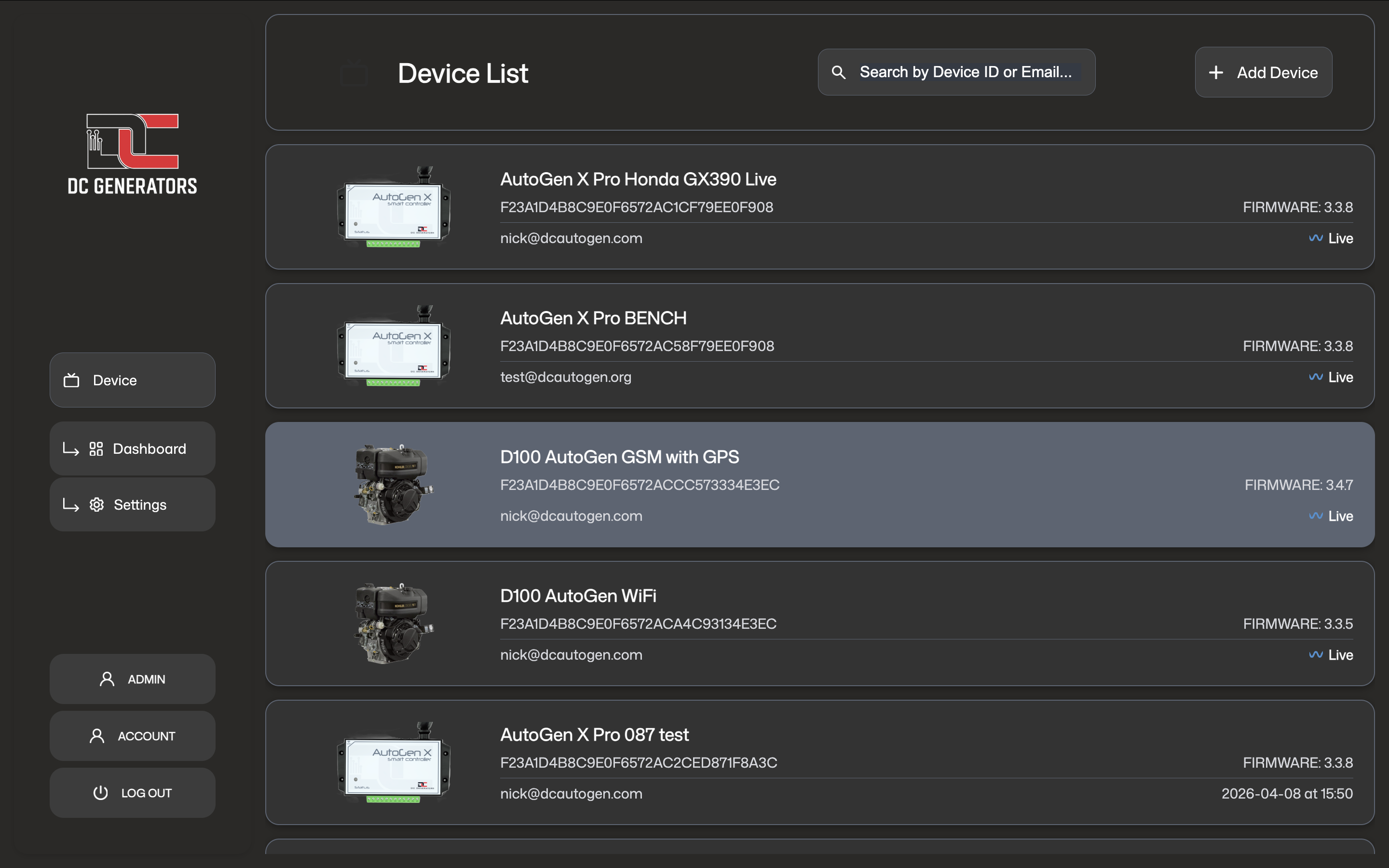
Use the device list to select the correct generator and confirm it is linked to your account.
Use the dashboard for live status, main controls, runtime, and current operating readings.
Web Dashboard Guide
The web dashboard gives a larger management view from a computer or tablet. It is useful for checking status, confirming firmware version, reviewing runtime, and adjusting supported settings.
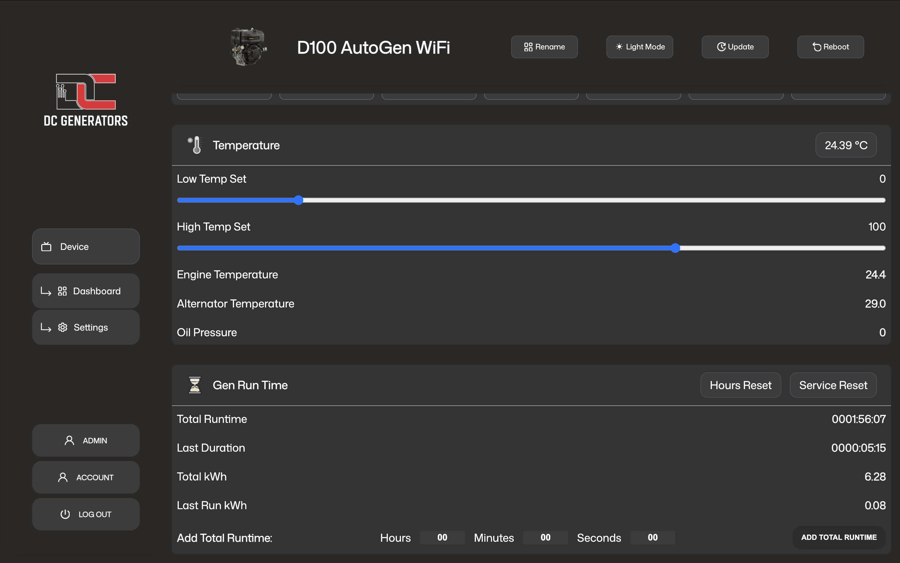
Monitoring And Readings
Engine Temperature, Alternator Temperature, and Environment Temperature. These readings are used for monitoring, thermal protection, and charging-current derating.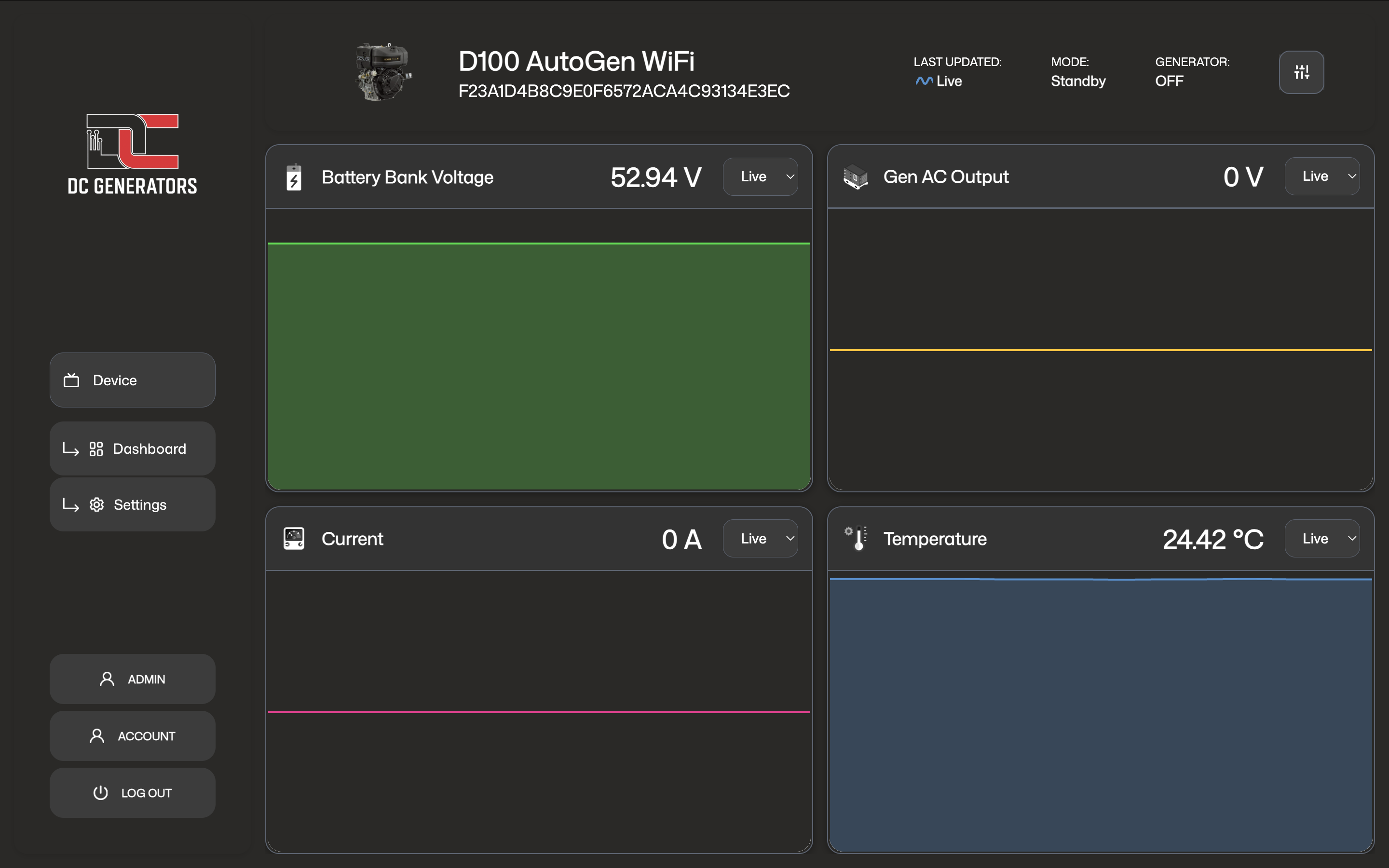
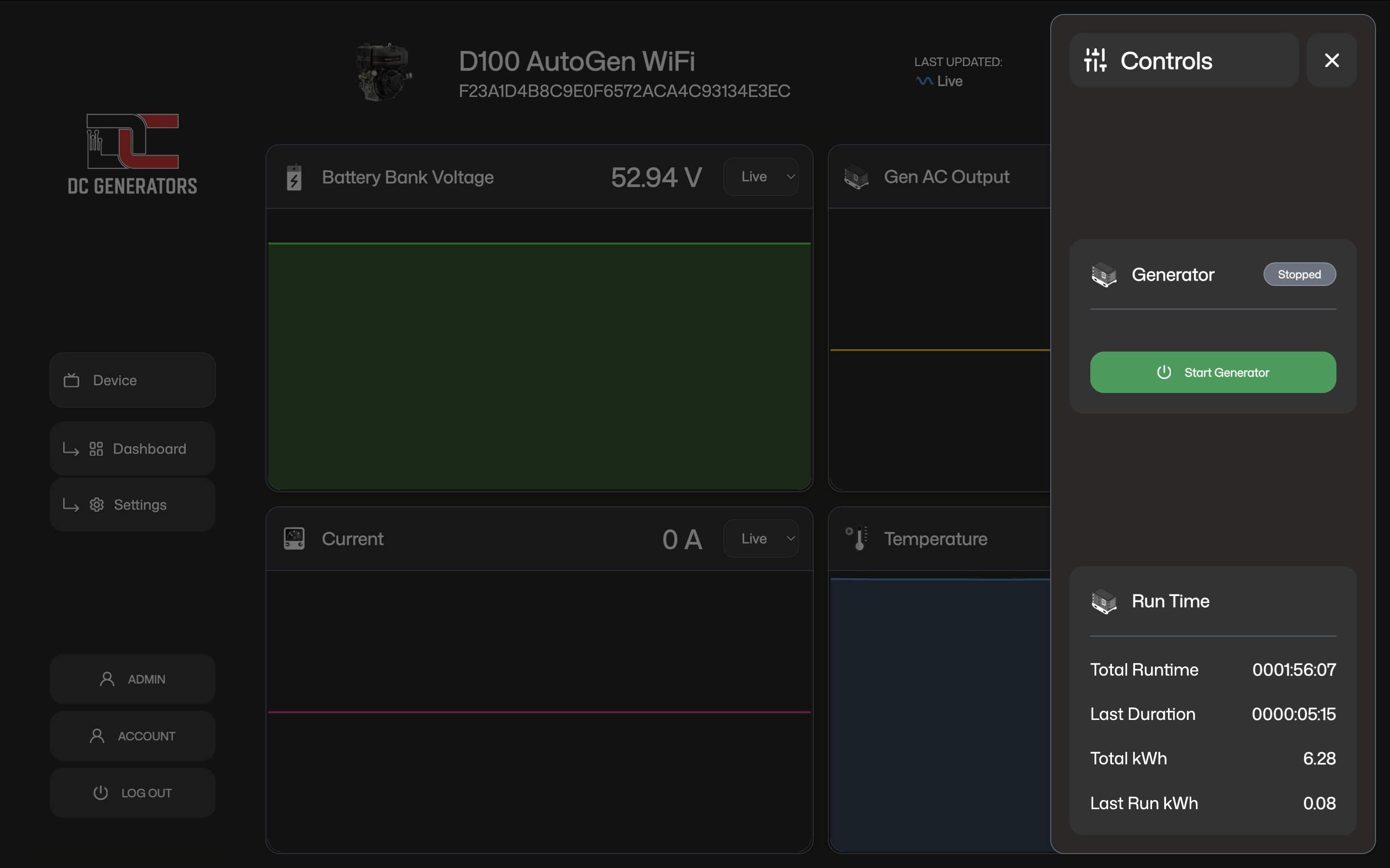
Manual Control
Manual control actions are managed sequences, not instant on-off commands. When you press Start, the system begins a start sequence and waits for running confirmation. When you press Stop, it performs a controlled shutdown sequence.
Used when the generator is ready to begin a run cycle from standby or another valid waiting state.
Used when the generator is running and you want the system to return to a stopped or waiting state.
Reset only after the cause is understood. Reset clears the state. It does not remove the real cause if the problem is still present.
Button Actions And What To Expect
These button actions are managed requests to the controller. They do not bypass the normal safety, confirmation, and shutdown logic.
When you press Start, the controller begins a managed start sequence. The generator may crank, pause, retry, and confirm that it is actually running before it enters charging states such as Bulk Charge or Absorb Charge.
A short period where the system is starting but not yet bulk charging is normal. The controller must first confirm a successful run before charging begins.
When you press Stop, the controller performs a controlled shutdown. The generator may take a short time to return to standby.
Reset clears an error or latched fault state so the unit can be started again if conditions are valid. It does not remove the original cause.
Front button behavior in firmware
The physical front button uses timing-based actions in the firmware. It does not behave exactly like the app buttons.
1.5 seconds. In Standby or Check, it requests a manual start. In running or charging-related states, it requests a stop.25 seconds after power-up.3 to 10 seconds. When released, it starts local WiFi AP mode.10 seconds or more. When released, it performs a forced stop.10 seconds or more, the firmware can also force a start while the button is still being held, but only from Standby and only when the system is ready.Automatic Operation
Battery-based automation
In many installations, the generator starts when battery voltage falls below the configured start threshold and stops when voltage rises above the configured stop threshold.
External operating logic
Some systems use additional control logic such as 2-wire start conditions, model-specific run confirmation methods, or installed signal inputs selected by the installer.
Temperature-based behavior
Where supported by the hardware and installation, temperature readings can be used for monitoring, protection, low-temperature start logic, high-temperature shutdown protection, and thermal derating of charging current before a full shutdown condition is reached.
Charging Stages And Charge Settings
Bulk is the main charging current target. It defines how hard the system charges during the main recovery phase. Higher bulk current charges faster, but it can also increase heat and electrical stress.
Absorption is the later-stage charge voltage target. Once the battery voltage reaches this level and charging conditions remain valid, the system transitions from the bulk stage into absorb.
Tail Current is the low-current threshold used near the end of absorption. It helps the system recognize that the battery bank is approaching charge completion.
In simple terms, the system charges hard using the bulk current target, transitions into absorb once voltage reaches the absorb target, and then watches current near the tail-current region to decide when the charge is effectively complete.
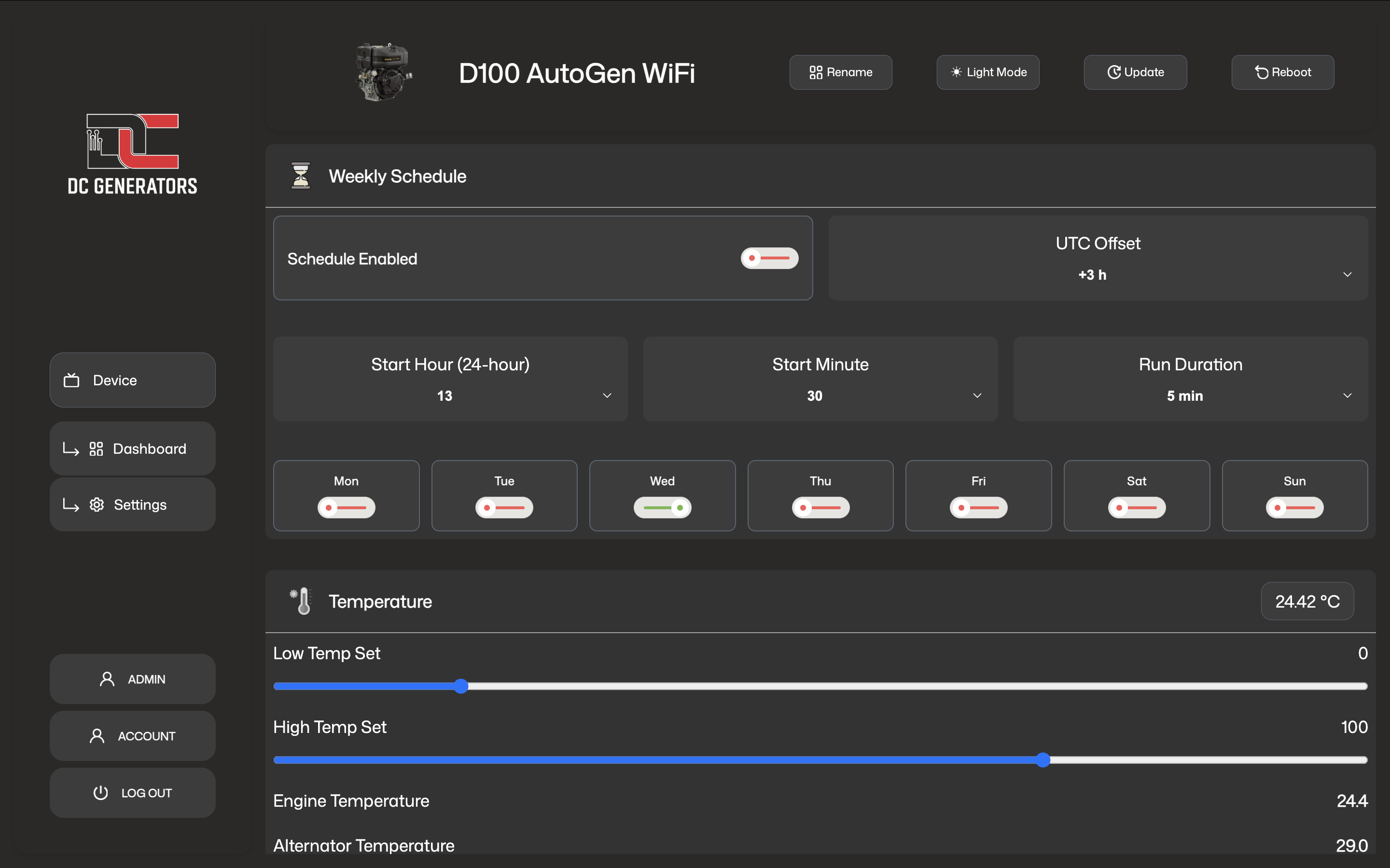
Weekly Schedule
Some AutoGen generator models support a weekly schedule timer. When enabled, the system can start on selected days at a configured time and run for a configured duration.
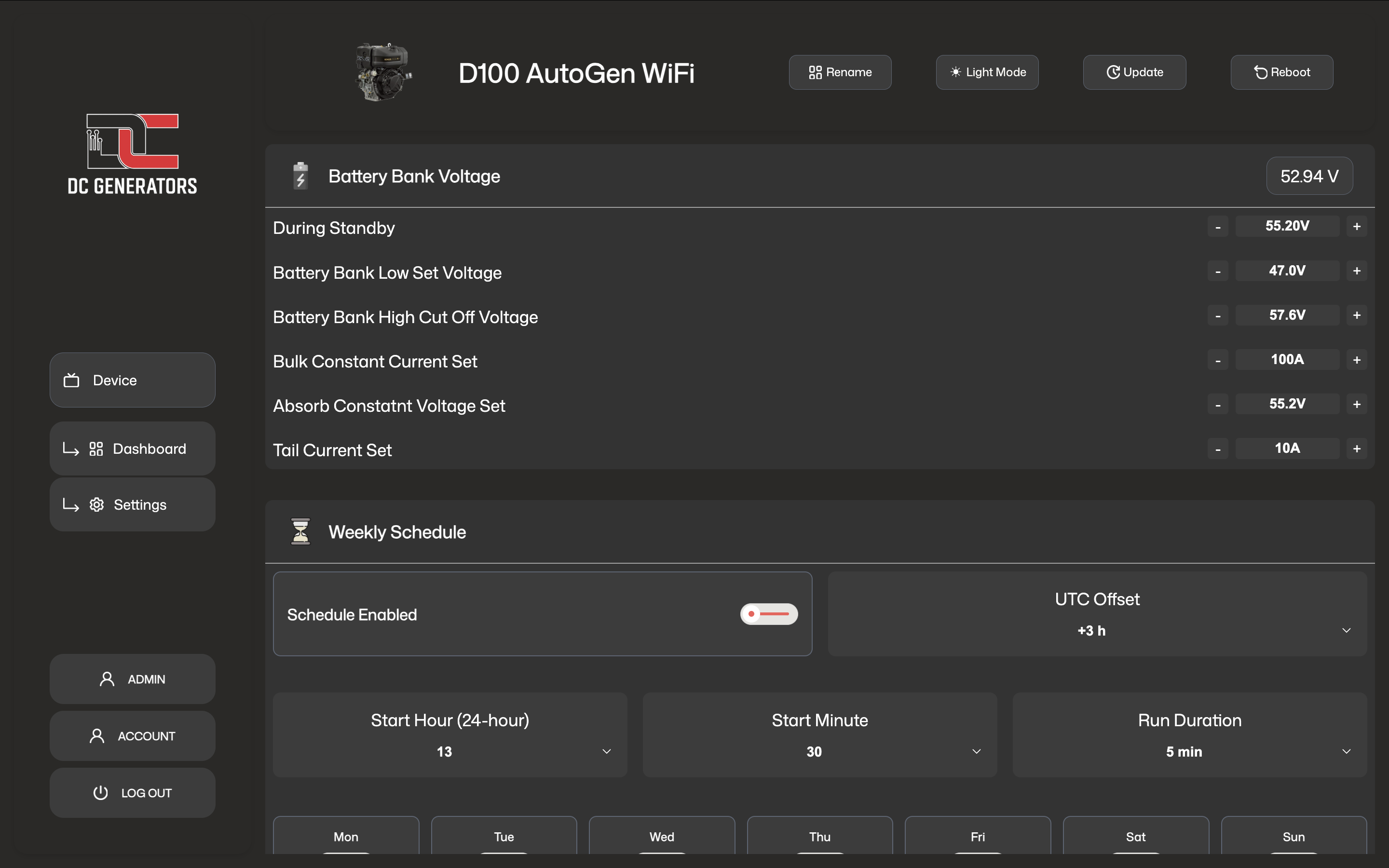
- schedule enabled
- selected days
- start hour
- start minute
- run duration
- time offset
After changing a schedule, confirm the device remains online and that the updated values appear correctly in the dashboard.
Important Settings
Status LED Guide
The status LED is used to show boot state, connectivity state, local access mode, and firmware update activity.
The controller is booting or starting up.
The controller is powered but not yet connected to the AutoGen cloud.
On GSM and GPS models, the modem or GPRS connection is being brought up.
The controller is connected to the AutoGen cloud and operating normally.
Local WiFi access point mode is active for local setup or local OTA access on supported models.
The front button is being held and the controller is recognizing the hold before the selected action is triggered.
The controller is in an error or protection state.
OTA update patterns
The LED alternates red and green three times before the download begins.
The LED blinks red six times, then returns to normal operation.
The LED rapidly alternates blue and cyan while the firmware file is being transferred.
The LED shows blue, white, cyan, then turns off before the device restarts.
A repeating red SOS-style blink pattern means the firmware update did not complete successfully.
Error States And Recovery
Error states are protective. They usually mean the system did not receive the confirmation needed to continue safely, not that the hardware itself is necessarily damaged.
- repeated failed starts
- lost running confirmation
- unsafe or invalid operating conditions
- Confirm what the generator actually did.
- Review running-signal readings and device status.
- Reset only after the cause is understood or corrected.
Timers And Runtime
Runtime values help confirm how long the generator actually operated and support maintenance planning.
The accumulated recorded operating time.
The most recent completed run, or the current run duration while running.
Care And Good Practice
Review key readings after service work, wiring changes, or unusual generator behavior.
This helps when more than one generator appears in your device list.
Do not assume a start command succeeded without checking status and running confirmation.
If faults repeat, investigate the real cause instead of repeatedly clearing the error.