Models Covered
AutoGen Ultra is built on the Unified controller hardware with the Ultra firmware profile. The installed communication variant determines how the controller reaches the AutoGen cloud.
Uses BLE for provisioning, WiFi station mode for cloud access, and local AP mode when WiFi credentials are missing, cloud access times out, or local access is requested.
Uses a cellular modem for cloud access. GPS telemetry is available where the fitted hardware and signal conditions support it. APN setup is done through the BLE terminal.
Quick Start
Apply controller power and wait for startup. The LED starts solid red during boot.
Provision WiFi credentials on Ultra WiFi, or set the APN on Ultra GSM/GPS.
Use the AutoGen Pro app to scan the QR code and add the device to the correct account.
Confirm online state, firmware version, voltage, run signal, temperature, runtime, and diagnostics.
Claiming AutoGen Ultra
Claiming links the Ultra controller to your AutoGen account. In the AutoGen Pro app, open the claim or QR scan workflow, scan the device QR code, give the unit a clear name, and confirm the claim.
Ultra Workshop, Ultra GSM Yard, or Ultra WiFi Plant Room so the right controller is easy to identify later.Connectivity
Ultra WiFi
Ultra WiFi stores WiFi credentials in the controller and connects as a WiFi station. After WiFi association succeeds, it opens the AutoGen cloud connection on port 3000, sends its device ID, synchronizes settings, publishes telemetry, and enters normal connected operation.
Use the WiFi provisioning flow, or send a BLE JSON command with {"cmd":"wifi_config","ssid":"network","password":"password"}.
Use wifi ssid <ssid> and wifi pass <password>. Use wifi_status to check stored credentials, station state, cloud state, and AP state.
Ultra GSM/GPS
Ultra GSM/GPS uses the fitted cellular modem. Insert an active data SIM, connect over BLE, open the terminal, and set the APN before expecting cloud connectivity.
- Open the AutoGen Pro app and connect to the controller over BLE.
- Open the BLE terminal.
- Send
apn set <your_apn>. Example:apn set cytamobile. - Send
apn showto confirm the stored APN. - Use
modemdiagfor modem diagnostics on GSM builds.
BLE Terminal
AutoGen Ultra advertises over BLE using an Ultra-specific device name. The BLE terminal is used for connection setup, local access, diagnostic checks, calibration, and service commands.
Connection and identity commands
wifi_status{"cmd":"wifi_config",...}ssid and password.{"cmd":"wifi_status"}wifi ssid <ssid>wifi pass <pass>wifiAutoGen_Local with password 12345678, then open 192.168.4.1.apn showapn set <value>apn set cytamobile.modemdiagsetid <id>idControl and status commands
startstopresetESP.restart().schedule or schedule statusrelay statusrelay test [ms]canstatRun-signal commands
runsig or runsig statusrunsig acrunsig dcrunsig scale <factor>runsig cal <actual-voltage>ac senseac sense onac sense offadc scanio35 rawPressure, throttle, choke, and oil commands
pressurepressure onpressure offpressure set <low> <high>pressure set 2.0 3.0.pressure dir normalpressure dir reversethrottle dirthrottle dir normalthrottle dir reversechoke dirchoke dir normalchoke dir reverseoil senseoil sense onoil sense offoil sense dir normaloil sense dir reverseUp/down arrowssfsbssCalibration and service commands
calhelpvcal <volts>vpin 35 <V>vpin 36 <V>dropcal <A> <V>dropcal showdropcal erasedropcal defaultslinedrop <A> <V>linedrop enablelinedrop disablelinedrop showlinedrop resetrc <val>showcalerasedefaultcalset <value>16-bit ADC build commands
vbat16 cal1 <V>vbat16 cal2 <V>vbat16 statusvbat16 clearactcsthrcs up <ms>thrcs down <ms>Local WiFi Access
Local AP mode starts a WiFi access point named AutoGen_Local. Connect with password 12345678, then open 192.168.4.1 from the app WiFi connection mode or a browser.
Send wifi in the BLE terminal, use the medium front-button hold, or let Ultra WiFi enter local fallback when WiFi/cloud connection is unavailable.
Local status, live values, controls, and supported local setup pages. Ultra cloud tasks pause or retry while local AP mode is active.
Dashboard Readings
Ultra publishes live telemetry approximately every 3 seconds while connected. The exact readings shown depend on fitted sensors, account scope, and firmware state.
Controls
Ultra control actions are managed requests. The controller checks state, readiness, run confirmation, and protection inputs before moving between states.
Starts from standby when the system is ready. Cloud commands, BLE commands, the local AP, schedule, and the front button can request a start.
Requests a controlled stop from running, starting, or stop-like states. Stop sources include cloud, BLE, local AP, and the front button.
Clears error states such as STATE_ERROR and 2-wire error states after the condition has been reviewed.
Aux relay manual control is available from the cloud where permitted and is echoed back to the dashboard.
Operating states
Ultra states include standby, starting, running, shutting down, error, check, start pause, post stop, auxiliary start/running/pause, 2-wire auto start/running/pause/error, checking, and service lock.
Front Button Actions
1.5 seconds. Starts from standby/check states when the system is ready, or requests stop from running, starting, or stop-like states.3 to 10 seconds. Starts local WiFi AP mode after release.10 seconds or more. Requests a force stop after release.10 seconds while still pressed, the firmware can request a start from standby when the system is ready.Choke Operation
AutoGen Ultra uses the secondary actuator channel for choke control. In the active firmware profile, the choke actuator is driven during each start attempt, then held or returned depending on the result.
3000 ms, while the starter can remain active up to the 5000 ms crank limit.8000 ms. After that, both choke actuator outputs are held off.5000 ms and retries. It allows up to three attempts.Cold engine example
On a cold engine, the choke may be needed for the first crank. Ultra engages choke for the first 3000 ms of the attempt. If the engine catches, the controller stops cranking, begins returning the choke, and continues to monitor run proof. If the engine does not catch, the controller releases the starter, waits 5000 ms, and tries again.
Warm engine example
On a warm engine, run proof may arrive quickly. The choke drive still starts with the attempt, but the controller stops cranking as soon as run proof is confirmed and commands choke return. In practice, the warm engine should spend less time cranking and transition to running sooner.
choke dir reverse. To return to normal direction, use choke dir normal. Check the current setting with choke dir.Throttle Actuator And Pressure Sensing
AutoGen Ultra reserves the primary actuator channel for throttle movement. The active firmware keeps normal automatic throttle chasing disabled unless pressure-based throttle control is explicitly enabled and saved.
pressure on has been used and saved.0.0 to 4.5 V pressure transducer to 0.0 to 10.0 bar.1.4545.2.0 bar, high target 3.0 bar.80 ms actuator pulse.1500 ms between pressure-control corrections.How pressure control works
If pressure is below the low target, the controller pulses throttle in the direction that increases pressure.
If pressure is above the high target, the controller pulses throttle in the direction that reduces pressure.
If pressure is between the low and high target, the controller holds the throttle actuator.
If the controller is not in a running state, pressure control is disabled, or the pressure value is invalid, the throttle actuator is held.
Example: enabling pressure control
pressure. Confirm sensor voltage and pressure reading are valid.pressure set 2.0 3.0 to use a 2.0 to 3.0 bar operating band.pressure dir normal or pressure dir reverse so throttle corrections move in the correct physical direction.pressure on. The setting is saved in flash.pressure off. The throttle actuator is held and the disabled state is saved.Example behavior
With the band set to 2.0 to 3.0 bar, a reading of 1.7 bar causes an 80 ms throttle-up correction, then the controller waits 1500 ms before checking again. A reading of 3.4 bar causes an 80 ms throttle-down correction. A reading of 2.5 bar holds the actuator.
Important Settings
AC or DC run-confirmation mode, with calibration scale for the selected mode.Weekly Schedule
Ultra supports weekly schedule settings over cloud and BLE status reporting. The schedule can enable selected days, a start hour, start minute, run duration, and UTC offset.
Enabled, hour, minute, duration from 1 to 1440 minutes, UTC offset from -12 to +14, and weekday selections Monday through Sunday.
GSM schedule operation uses modem time. WiFi schedule operation uses the cloud/WiFi task timing path and synchronized settings.
Diagnostics
Diagnostics are available from the single-device Manage page for supported Ultra controllers. Use the event stream to review starts, stops, retries, run confirmation, protection shutdowns, service locks, and recovery actions.
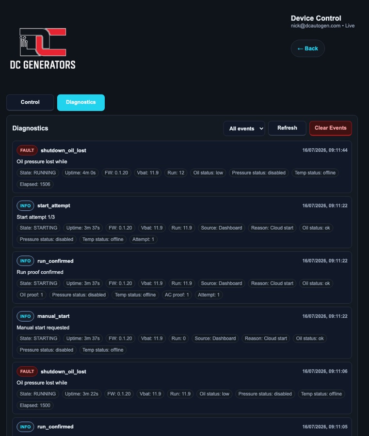
manual_start, manual_stop, reset, boot_recovery, service_lock, start_attempt, run_confirmed, start_attempt_failed, and protective shutdown events.
Events include timestamps, source, reason, run-signal mode, temperature status, pressure status, oil status, state, and related live values where reported.
Firmware Updates
Ultra firmware uses the dedicated Ultra firmware policy path and is isolated from X Pro and DC Generator releases. Updates can be normal checks or forced checks depending on operator permission.
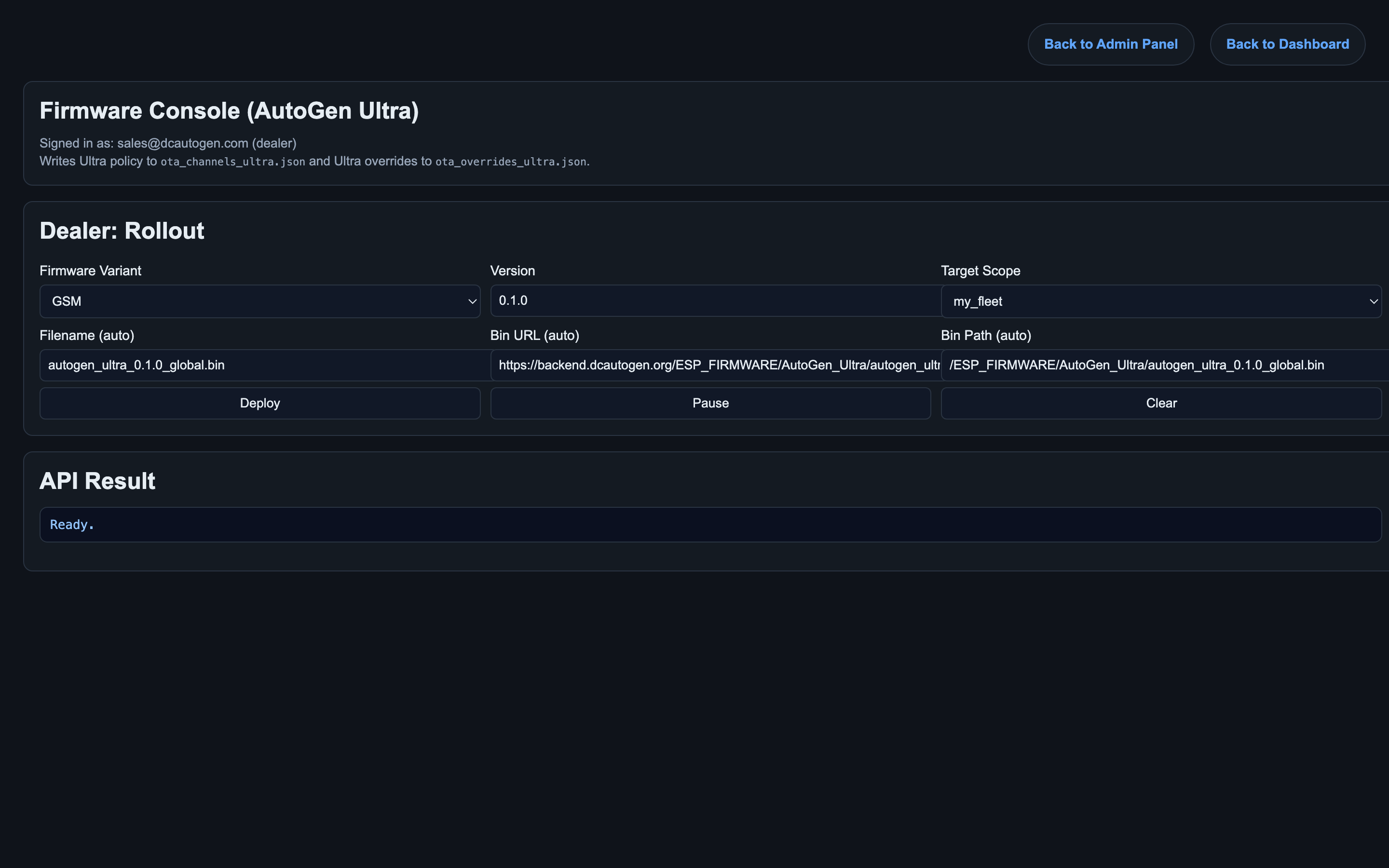
Downloads through the WiFi cloud connection using the WiFi HTTP client path.
Downloads through the cellular data connection using the GSM HTTP client path. Reconnect can take longer after restart.
Status LED Guide
The controller is booting or starting up.
The controller is not connected to the AutoGen cloud. The LED toggles red on and off every 1000 ms.
On Ultra GSM/GPS, the modem or GPRS connection is being brought up.
The controller is connected to the AutoGen cloud. The LED toggles green on and off every 1000 ms.
Local WiFi AP mode is active. The LED toggles magenta on and off every 100 ms.
The front button is being held. The LED toggles red on and off every 500 ms.
The controller is in an error or protection state. The LED toggles red on and off every 250 ms.
OTA update patterns
The LED alternates red and green three times. Each color is shown for 180 ms.
The LED blinks red six times at 180 ms on and 180 ms off.
The LED alternates RGB(0,180,255) and RGB(0,0,255) every 90 ms while firmware data is being transferred.
The LED shows RGB(0,0,255), RGB(255,255,255), RGB(0,180,255), then off. Each step lasts 160 ms before restart.
The repeating red SOS-style sequence uses short 180 ms pulses, long 540 ms pulses, and a 900 ms pause.
Error States And Recovery
Error states are protective. Review the state, diagnostics events, run confirmation, oil pressure, pressure control status, temperature readings, voltage, and service conditions before resetting or restarting.
Failed start confirmation, run signal loss, low oil status, high temperature, service lock, cellular or WiFi drop, or invalid operating conditions.
Reset clears the controller state after review. It does not remove the underlying cause if the same condition remains present.